Trailer Brake Wiring Diagram
The black wire is the power supply line to the brake control. The manual adjusting brake will not have this wire running across the inside of the assembly.
Breakaway Trailer Brake Wiring Diagram Collection Wiring Diagram Sample
Another way to identify between the two is the bottom spring.

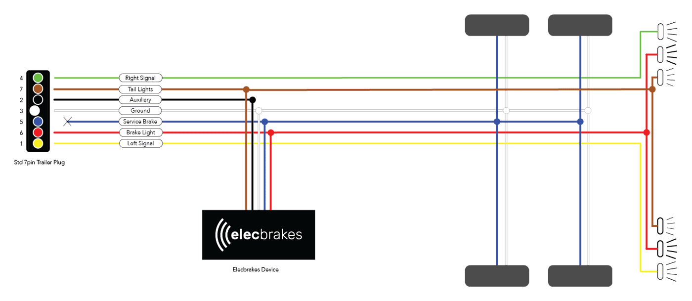
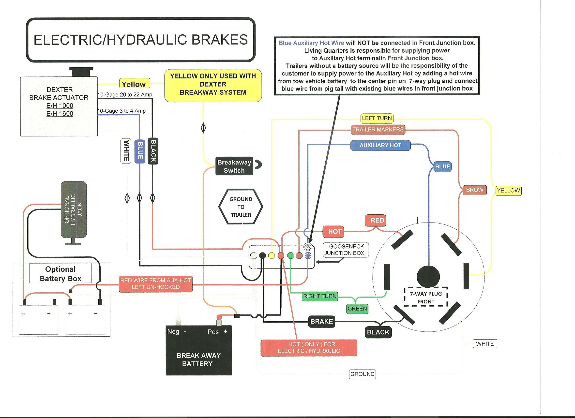
Trailer brake wiring diagram. The blue (brake output) wire must be connected to the trailer connector’s brake wire. As the name implies, they use four wires to carry out the vital lighting functions. Auxiliary connection is optional, it may be connected to any 12v to 24v constant power source or left unconnected.
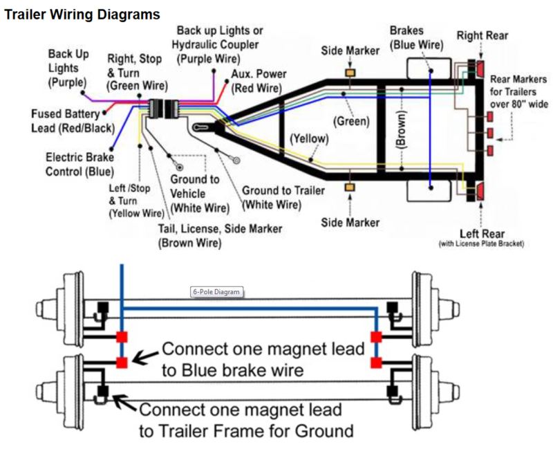
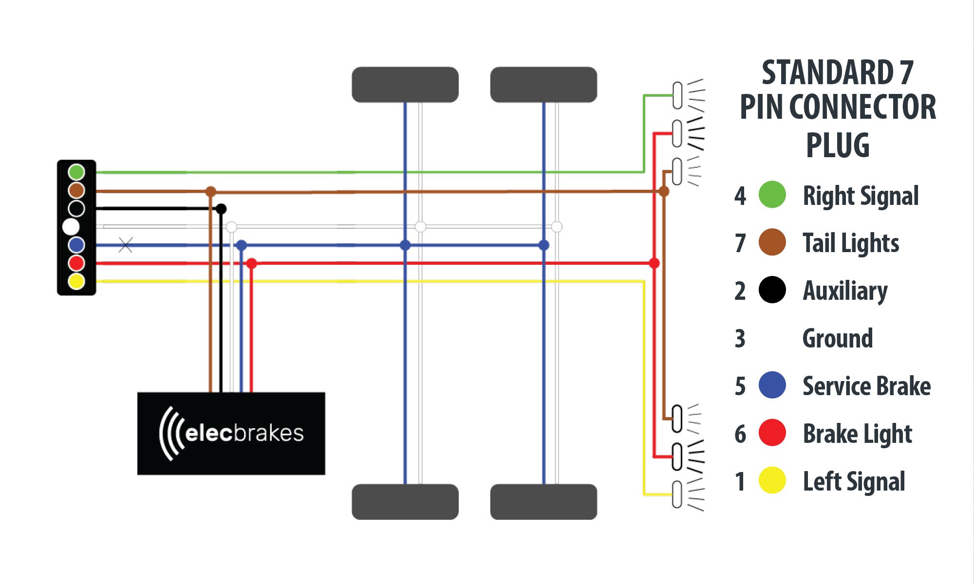
The trailer wiring diagram shows this wire going to all the lights and brakes. 7 way trailer wiring diagram is explained in details in the picture and the table below: This wiring electric trailer brakes diagram model is more acceptable for sophisticated trailers and rvs.
Break away systems may be added to the service brake circuit. Trailer wiring connectors various connectors are available from four to seven pins that allow for the transfer of power for the lighting as well as auxiliary functions such as an electric trailer brake controller, backup lights, or a 12v power supply for a winch or interior trailer lights. Electric brake controller wiring diagram.
As stated earlier, the lines in a 7 pin trailer wiring diagram with brakes signifies wires. It displays the electric aspects of the circuit as straightforward shapes, and additionally the link and power connections in between those items. Assortment of electric trailer brake wiring schematic.
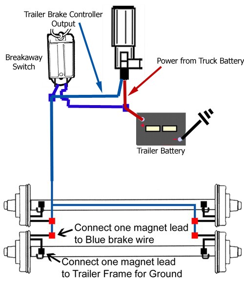
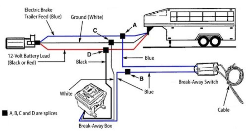
They also provide a wire for a ground connection. We then run a jumper wire from the electric brake power wire to the right side brake assemblies (see photo). Blue wires are interchangeable on the break away switch 3.
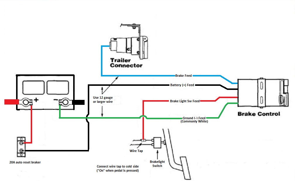
White pin to your floor. The red (stoplight) wire must be connected to the cold side of the brake pedal stoplight switch. This page has wire diagrams for many electric options including wires for trailer lights brakes alt power and connectors.
It symbolizes the power circuits elements as easy styles, using the genuine power and floor links between the two as coloured sectors. Trailer wiring diagrams trailer wiring connectors various connectors are available from four to seven pins that allow for the transfer of power for the lighting as well as auxiliary functions such as an electric trailer brake controller, backup lights, or. White pin for the ground.
The four wires control the turn signals, brake lights and taillights or running lights. But, it doesn’t mean link between the cables. Do not disturb the position of the switch.
Blue = electric brakes or hydraulic reverse disable (see blue wire notes below.) Splice one blue wire of the break away switch to the electric brake wire coming from the trailer side connector a see diagram on next page. The following diagram is a general guide for wiring common brake controllers into cars.
Do not disturb the position of the switch. The fsa brakes will have a wire that will run from about 9 o’clock to 1 o’clock. There is additional wiring involved in tying your braking system and battery power to the rear plug, which activates the trailer.
Splice down line from the switch; On the 1 o’clock side it will have a banjo looking fitting (shown to the left). The black wire is the power supply line to the brake control.
A wiring diagram is an ordinary pictorial representation of a intricate electrical circuit. Trailer plugs are cheap and extremely easy to swap out, all you need is a screwdriver and the ability to remember where the wires went. It reveals the parts of the circuit as streamlined forms, as well as the power and signal connections in between the gadgets.
The blue (brake output) wire must be connected to the trailer connector’s brake wire. A brake controller wiring installation kit makes light work! Splice down line from the switch;
The red (stoplight) wire must be connected to the cold side of the brake pedal stoplight switch. Sometimes, the cables will cross. Injunction of two wires is usually indicated by black dot on the junction of 2 lines.
December 12, 2021 · wiring diagram. There will be primary lines which are represented by l1, l2, l3, and so on. A wiring diagram is a kind of schematic which uses abstract pictorial symbols showing every one of the interconnections of components in a very system.
The 5th pin, a blue wire, gives power to operate (or disable) the trailer brakes. It represents the physical elements of the electric circuit as geometric forms, with the actual power and connection links between them as thin sides. A wiring diagram is a streamlined conventional pictorial representation of an electric circuit.
Brown pin for unwanted markers, tail lamps, and running lights. Wiring diagram for tandem axle trailer best breakaway kit. The trailer brakes are activated electronically by the use of a brake control box mounted under the dash in the tow vehicle.
7 way plug wiring diagram standard wiring* post purpose wire color tm park light green (+) battery feed black rt right turn/brake light brown lt left turn/brake light red s trailer electric brakes blue gd ground white a accessory yellow this is the most common (standard) wiring scheme for rv plugs and the one used by major auto manufacturers today. It can be made use of as a resource of information, or as a tool for building.
Wiring a Trailer Breakaway Kit on a Bigfoot Travel Trailer
Instructions to Wire a Trailer for Electric Brakes
Wiring Diagram On Trailer Brakes Trailer Wiring Diagram

Electric Brake Trailer Wiring Diagram Collection Wiring Diagram Sample
Electric Brakes For Trailer Diagram

Winning at Trailer Brake Wiring Champion Trailers Blog

Trailer Wiring Diagram With Electric Brakes Wiring Diagram
Trailer Brake Wiring Diagram Simple Electric Brakes Wiring Solutions Best Of Trailer Diagram
Electric Trailer Brake Wiring Schematic Free Wiring Diagram

How do Trailer Brake Wire to Trailer Wiring.
How to Wire Up Electric Trailer Brakes It Still Runs

Wiring Diagram For A Trailer With Electric Brakes Trailer Wiring Diagram

Electric Trailer Brake Wiring Schematic Free Wiring Diagram

Trailer Brake Wire Diagram Installing Electric Brake Controls on 24 Volt Vehicles etrailer

Wiring Diagram for Utility Trailer with Electric Brakes Gallery

Electric Trailer Brake Wiring Schematic Free Wiring Diagram

Trailer Breakaway Wiring Schematic Free Wiring Diagram

Wiring Diagram for Utility Trailer with Electric Brakes Gallery

trailer wiring question